Table of Contents
Overpaneling
Overpaneling has two related meanings; both refer to having more solar panel output than a system might otherwise require.
- Most common meaning: overpaneled charge controller - battery bank and charge controller are evenly matched; panel nominal or actual output is more than the MPPT controller's rating. This is the most common meaning. Note: PWM controllers should not be overpaneled as they have no way to limit incoming current to protect themselves.
- Less common meaning: overpaneled battery bank - solar panels and charge controller are evenly matched; both are oversized compared to battery bank.
Note: overpaneling is not overvolting, which would be exceeding the maximum input voltage of the charge controller. Overvolting often results in damage to the controller; it can be caused by linking too many panels in series, or running too close to the voltage max in conditions that raise the panels' Voc.1)
vs. charge controller
TL;DR: overpaneling the controller means sizing MPPT for actual incoming solar power rather than rated panel wattage.
 Overpaneling, or having “too much” panel for the rating of your MPPT charge controller, can be desirable in some situations. It is a trade-off that biases the setup to get more power out of normal and marginal conditions at the possible expense of the peak output during optimal conditions.2)
In car terms, the overpaneled system trades away some of the panels' top-end output for more low- and mid-range grunt. – secessus
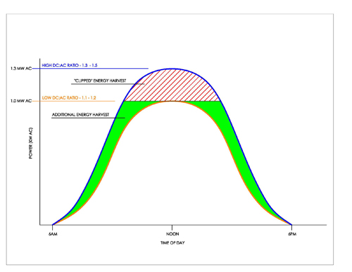
The overpaneled system's power output bell curve is shifted upwards and cut off by the controller when it reaches its limits. This is known as clipping, trimming, or clamping due to the “flat top” appearance of the overpaneled output curve.
With appropriate overpaneling the clipping is relatively minor. Victron notes that:
Generally total energy harvested from a 130% panel oversizing results in less than 1% annual energy loss. – source
theory
Consider the image to the right.3) The smaller/interior bell curve is the normally paneled configuration.
The larger/exterior curve is the overpaneled configuration.
The striped area is the peak power “clipped” by the controller when the controller is overpaneled.
The horizontal line is the peak output of the normal and overpaneled configurations; they are both capped at the controller's rated output.
The green area is the additional power produced during suboptimal conditions. These areas are sometimes called shoulders due to their shape.
Overpaneling might be a good fit for you if your MPPT controller is designed to clamp down on excessive power without damage and
- you want to get the most out of “shoulder” periods
- you want to get deeply cycled batteries charging as early as possible in the morning
- you spend most of your time in areas with marginal insolation, like the Pacific Northwest
- you spend time in partial shade
- you want to use a smaller controller instead of jumping up to the next size. Example, 43A max output and your choices are 40A or 60A controllers.
example
Let's say you want to adhere to Victron's 10-30% overpaneling approach. Working backwards, their model appears to use 14.2v Vbatt as a constant.
- 500w / 14.2v = 35.2A.
- 35.2A on a 30A MPPT is 17.3% overpaneled: ( (35.2 - 30) / 30 = 0.173)
MPPT and heat
Overpaneling can increase heat in PPT charge controllers
- during late absorption phase; and
- when there is very little load being used
This occurs because the PPT controller moves Vpanel toward Voc to reduce current when less is needed but battery voltage is high, as in late Absorption. For this reason adding some load to the system in Absorption can reduce PV voltage (and therefore CC temps) to lower levels.4)
clipping is relatively uncommon
[This section is based on a forum post - secessus]
Perhaps counterintuiitively, overpaneled systems in normal5) conditions don't need to constrain power that often. A couple reasons for this:
- Overpaneled systems start collecting usable power earlier in marginal light. Secessus observes that by the time the sun is high enough to theoretically max out the controller, it has already completed Bulk and the bank's current acceptance is dropping.
- Because of temperature derating the panels will usually be peaking at something like 75% of rated power. Yes, perfect storms of altitude and cold can yield max+ power; that is when clamping/limiting kicks in.
how MPPT controllers clip power
[note: this section was based on a forum post and is therefore more personal in style – secessus]
 The ability of MPPT controllers to clip power is a function of their ability to select arbitary powerpoints, thereby forcing the panel to produce the amount of power associated with a given powerpoint.
Fictional example:
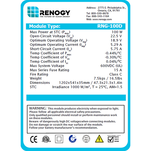
- 100W Renogy mono panel, RNG-100d, under laboratory conditions
- 5A MPPT controller
- Vmp == 18.9, Imp == 5.29.
- battery in Bulk, 13v at the moment
If the controller was rated at 10A it would run the panel wide open at Vmp (18.9v). That would mean ~7.7A going into the battery.6)
But that can't happen because the 5A controller is undersized. 5A output at our present 13v charging voltage would be 65w, quite a bit down from the rated 100W. The controller protects itself by forcing the panel to produce less power.7) This is called clamping, clipping, current limiting, overcurrent protection and a few other marketing terms.
the gory details
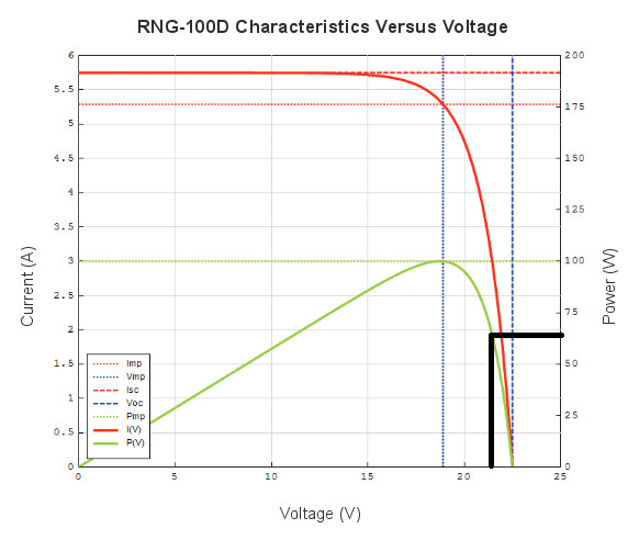
 Consider the power curve for this panel:
The dotted green line is Pmax (max power). The solid green line is the “power curve”. The heavy horizontal black line is at 65w.8)
The intersection of Watts and Volts on the curve is a power point.9)
The heavy vertical black line10) comes down from that intersection at 21v.11)
In this case the controller wants to limit panel output to 65w So it runs the panel at 21v, which is a far cry from Vmp. Then it downconverts the excess voltage to amps: it charges the battery12) 5A @ 13v. This same mechanism is used to reduce power in Absorption and Float stages.
corollaries
If you have the curve and Vpanel you can derive the power output.
If you have the curve and you know Wpanel you can derive Vpanel.
If you have a lot of time and patience, you can plot Vpanel and Wpanel to draw the curve yourself.
An MPPT controller is always Tracking and using powerpoints, not just when the Maximum Power Point is required.
vs. battery bank
In this configuration there is abundant solar power and relatively little bank capacity. This is sometimes called underbanking.
“…the person draining their batteries to the 50% range regularly would do much better with a 2 watts to 1Ah ratio, or even 3 to 1.” – SternWake13)
Overpaneling the bank gets lead-acid batteries charged faster14) and keeps them charged longer than other approaches. This minimizes battery murdering partial state of charge conditions found in overbanking.
Overpaneling the bank would work best when:
- you want your lead-chemistry batteries to stay as charged as much as possible
- you are in an area with relatively little sunshine
- you are in a position that has a limited time window of clear sun
- you want to save battery weight
- you want to reduce battery investment and complexity
- the bulk of power is consumed in the daytime and relatively little at night (cf. opportunity loads)
- you spend most of your time in an area with many hours of good sun15)
- you want deeply discharged batteries to get charged as soon as possible in the morning
Since the underbanked system has less capacity will reduce your actual reserve days of power to some extent. But during daytime there is some solar power coming in and an overpaneled configuration will harvest relatively more power in sub-optimal conditions. The smaller bank will get through Bulk and well into Absorption faster, too. This will help extend the effective reserve days of power.
Further reading:

