User Tools
This is an old revision of the document!
Table of Contents
Battery to battery chargers
TL;DR
- they are usually rated on their charging output: 20A, 40A, etc. For technical reasons the input from the alternator will often be somewhat higher than the output: (25A, 45A, etc)
- the DC-DC needs to be sized appropriately for both the alternator and battery bank
Limitations
The major downside to DC-to-DC chargers is cost, especially when compared to how many amps they can pass when compared to plain isolators might pass as much current as the alternator, battery, and wiring could handle. This isn't as big a limitation as it might seem since lead-acid current acceptance drops substantially throughout Absorption, and lithium owners often limit charging to C/5 for maximal longevity.
However, for those with absurdly gigantic (like 10kWh+) battery banks, alternator setups, and wallets, DC-DC chargers up to 200amps are available. [Untested theory: b2b chargers might work well beside normal isolators; this is essentially the $$$ CTEK SmartPass setup described below.]
In addition, even DC-DC chargers can fail to charge lead batteries fully. Lead-acid batteries require two things to get fully charged:
- a high enough Absorption voltage (Vabs) - DC-DC chargers handle this nicely.
- enough time at that voltage for the battery to stop accepting much current.1) If you aren't driving for (say) 5 hours then the charger can't charge for 5 hours to meet the battery's needs. 2) This is where a bit of solar helps with the long-duration duties.
DC-DC chargers are often triggered by the IGN circuit, but voltage sensing can be added to that circuit. Others are triggered by chassis-side voltage alone.
DC-DC chargers typically do not support self-jumpstarting, although the need for jumpstarting may be reduced with combo units (below) that maintain the starter battery from solar power.
Dual-input (alternator + solar) units make charging source decisions that are sometimes quirky. See below.
is DC-DC charging mandatory?
sizing
DC-DC chargers come in different ratings (10A, 40A, 60A, etc) which increase significantly in price as the rating increases. In general, the stated rating is on the output (battery charging) side.3) Since DC-DC chargers are usually boosting (increasing) voltage, a DC-DC charger will typically pull somewhat more current from the chassis than it provides to the house battery.
Example:4) - Remembering that W = V x A, 40A @ 14.4v (576w) to house battery would be
- 41A when chassis voltage is 14.0v (576w / 14.0v)
- 42A when chassis voltage is 13.8v (576w / 13.8v), as might be seen on older vehicles
- 48A when chassis voltage is 12.0v (576w / 12.0v), as could happen with a “smart” alternator, or if excess load pulls a single-voltage alternator down
The DC-DC should be big enough to meet your charging targets given the amount of driving you do and the contributions of other forms of charging. It should be small enough that the alternator can provide the power continuously.5) An oversized DC-DC charger cannot protect the alternator.
Note that bigger is not always better; different battery chemistries and capacities accept current at different rates. Buying more charging capacity than the battery wants6) is a waste of money. Buying more charging capacity than your alternator can deliver constantly can overheat/damage the alternator.
Assuming a 100Ah bank:
- Flooded lead-acid accepts a maximum of about 0.2C, or 20A and requires a minimum of 0.10C (10A). In this case, 10-20A of charging capacity would be appropriate. Less than 10A would be insufficient for battery health and more than 20A would be wasted expense.
- AGM lead-acid accepts a max of about 0.33C, or 33A per 100A of battery capacity, and requires a minimum of 0.2C (20A). In this case, 20-33A of charging capacity would be appropriate. Less than 20A would be insufficient for battery health and more than 33A would be wasted expense.7)
- Lithium has very low internal resistance and may be able to slurp up all the alternator has to give.8) 0.2C-0.4C charging may be the sweet spot between charging time and longevity, which would be 20A - 40A charging. If you are charging by alternator alone and have limited time to do so, some BMS allow up to 1.0C charging (100A). The bank will not be expected to last as many cycles or stay balanced under aggressive charging but the option is there for people who need it.
isolated chargers
Isolated DC-DC chargers have negative terminals output side (battery bank) “galvanically isolated” from the input side (alternator). It is not needed for most use cases:
Generally speaking, one only needs to isolate the negatives when the installation does not share a common negative return path, such as may be the case on many fiberglass boats that don't have a chassis and may not have a common grounding bus to which all their battery banks connect. – Justin Cook9)
But note that a trailer does not always have common grounding:
Galvanically isolated is a nice thing to have, especially if you are charging house batteries in a trailer from the tow vehicle engine. The issue relates to how the house battery is grounded to chassis ground when the tow vehicle is disconnected. All in one RVs and vans don't have this issue (probably) so I would not expect them to need galvanic isolation. (emphasis added) – HaldorEE10)
examples - combo with solar charge controller
Combining the solar charge controller and DC-DC charger in one unit can have benefits in cleaner/simpler installation, starter battery maintenance from solar, and perhaps cost over separate components. The downsides are less configurabilty11), single points of failure, and limited options on solar input.
Combo units typically have much lower maximum panel input voltages (as low as 23v) than a standalone charge controller would (60v - 150v). This limits the solar configuration in a few ways:
- series panel arrangements are effectively ruled out
- higher-voltage panels (nominal 20v, 24v) are effectively ruled out
- even nominal 12v panels with high Voc may be problematic. Poly panels, with their typically-lower Vmp/Voc, may be especially useful with combo units.
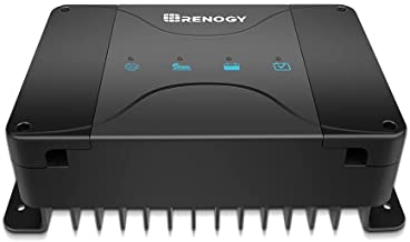
Renogy
DCC series
- DCC50S 50A model with MPPT charging. MPPT input limited to 25v.12) - manual (pdf) Total output is limited to 50A from either independent source (see below).
- a 30A combo model is also available
- low temp charging cut-off supported in Lithium profile when external temp probe is present
- voltage-sensing available
With the bluetooth dongle and app installed13), the profiles can be adjusted and power output reduced in 10A increments.
lithium profiles
- Low-temp cutoff on lithium profiles only. This may require the use of the external temp probe – the documentation is ambiguous.
- there is no Float in lithium profiles; the bank will wander between the Absorption (“Boost”) and Rebulk voltage setpoints rather than sit at a fixed Float.
solar+alternator behavior
This device's behavior regarding solar+alternator charging is widely misunderstood.
The 50A dual-input charger prefers to charge by solar if possible, up to 50A. If it cannot meet charging demands alone and the engine is running it will will charge up to 25A by solar and 25A by alternator:
charging examples
Using the above information and a theoretical scenario where we have 15A14) of solar charging available during the daytime, an alternator capable of delivering 50A, and a bank able to accept 50A of charging:
- driving at night: 50A alternator + 0A solar = 50A total charging
- parked in daytime: 0A alternator + 15A solar = 15A total charging
- driving in daytime: 25A alternator + 15A solar = 40A total charging
Behavior is the same for the 30A model (pdf) except 15A + 15A vs 25A + 25A above.
UPDATE: a Renogy comment on this video suggests the DCC series switches to alternator-only “when the PV is below around 15V, it charges at full capacity from the [alternator]”.
Note: some have reported better alternator charging performance with the D+ (smart alternator) wire connected, even with plain alternators. Oversizing cables from the alternator may also help. 15)
disconnecting the solar
Because of the behavior described above, people who want maximum alternator charging sometimes add a way to disconnect solar panels. This is typically done by adding some kind of disconnect on the panel POS wire going to the solar charge controller:
- manual switch
- NC (normally-closed) relay that is activated by D+. Key on = solar off.
- etc
starter battery maintenance behavior
If the service battery is in float charge stage, the starting battery will be charged at the same time. The charging voltage is limited at 13.8V. The charging amperage is limited at 25A.16)
Note: since the Renogy Lithium profile doesn't have a float stage starter battery maint may not be available in that profile.17) At least one report claims the starter battery is maintained in the Li profile.18)
Further reading: a post describing functionality of the charger
RBC series
Note: some manual versions brand this unit as part of the “Rego” line.
The RBC series 50A charger has a 50V PV input limit and built-in bluetooth. It can also boost 12v panel voltage to charge 24v banks. A RBC30 is reported to exist.
The existing manual is minimal and specs/behavior are largely undocumented as of Jan 2024.
solar+alternator behavior
- A marketing image indicates simultaneous charging (“solar panels and alternator… charge the battery simultaneously”).
- The product page says it “prioritizes solar energy”. no split logic is discussed in either source.
- a Youtube comment by Renogy on this video says “he product has a low current cutoff function, which switches to single-engine charging when the PV input current is below a certain value.” In another comment they say “When the PV is detected to be less than 7A, it will automatically switch to the alternator without the need for manual disconnection of PV”. This suggests that when combined charging falls <32A (25A alternator + 7A solar) it switches to 50A alternator-only charging (unverified).
Kisae
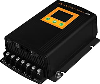 Kisae makes a DMT1230 30A and DMT1250 50A DC-DC charger; the rating refers to the alternator charging current. Both sizes have the same solar capacity:
- 30A of solar input current.22).
- They estimate this will be ~500w of actual input wattage23), with overpaneling allowed to 600w.
- supports termination of Absorption by tail current24)
The lithium charging logic is charge-and-stop:
- Bulk charge up to to the user-defined Absorption voltage at the user-defined current level (5A increments)
- hold Absorption voltage until charge current25) falls to the user-defined amount of trailing amps.
- stop charging
- until bank voltage falls to <13.3v
- then re-Bulk
Customer support is generally regarded as excellent.
- teardown for modification
- additional solar input information from a support email
- output current adjustable in 5A increments
solar+alternator behavior
When the alternator input terminals detect at least 13.2v the charger will be switched to alternator charging.26) This appears to be hardcoded:
With two inputs available, the house battery will be charged from either the engine while underway, or via the solar panels when stationary. The process to choose either engine or solar is fully automatic… – source (pdf)
starter battery maintenance behavior
The Kisae does not maintain the starter battery. However, the manual gives instructions on feeding power to the starter battery when that battery's voltage is too low:
For DMT1230, 1250 using CH 2 (Solar Array/Panel): Turn unit off. Use a proper jumper to temporary connected CH2 “+” to Ch 1 “+”. Remove the jumper when CH 1 is above the unit start up voltage (8Vdc) and restart the unit.
related
This unit also seems to be sold under the Ring and Merlin brands.
SRNE
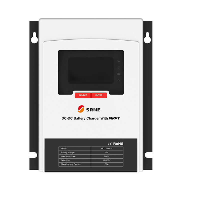
SRNE makes 30A and 50A combo unit similar to the Ring and Kisae. Since SRNE makes things that are rebadged by other sellers it is possible they are the original manufacturers. The BT dongle appears to be the same as the EpEver and Renogy models.
- output rating based on solar. 30A will actually do 35A from alternator, 50A will do 60A.
- PV input limit 55V, MPPT range 17v-36v
- alternator input 9v-17v. Connects at 13.2v, or at 12v if D+ is present.
- the controller has an input for voltage sensing – not confirmed working in the field yet
- Absorption duration 120min for lead chemistries, 0m for Li, and 10-600 for user-defined.
- low-temp charging might be controllable via external temp control feeding the remote switch: “the external switch can control whether the Controller can activate charging, the switch short-circuit can start charging and switching-off can stop charging”
solar+alternator behavior
The manual claims the charger can charge from both sources at once (“hybrid” or “Mode 3”); this may require setting the N13 value to SOLAR.27)
Like the Renogy DCC30 and 50, when charging from both sources each can only output 1/2 the rated current (25A solar, 25A alternator, for example).28)
starter battery maintenance behavior
The brochure claims the charger will maintain the starter battery from solar (“Mode 4”), apparently at 13v. Starter batt charging current ≤15A with the 30A model and ≤25A with the 50A.
Rich Solar
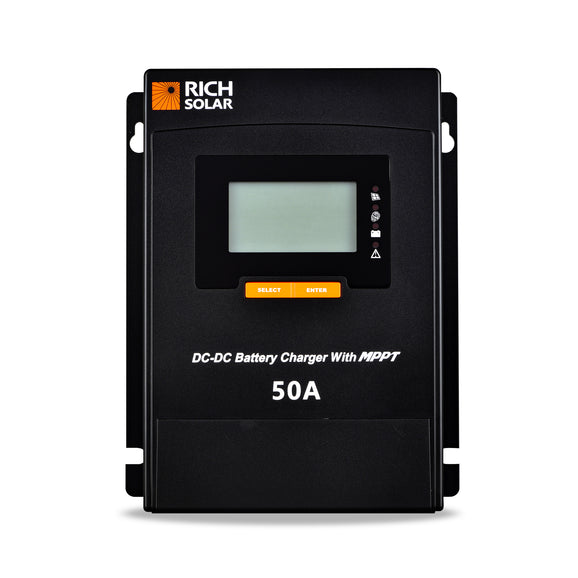
Rich makes a 50A DC-DC w/MPPT. It appears to be very similar to the SRNE listed above.
- Max. Voltage of Open Circuit: 55Vdc
- MPPT Voltage Range: 17-36Vdc
- Max PV Input Current: 45A
- Max PV Input Power: 700W
- Alternator input 13.2-16Vdc
- Smart alternator input 12.0-16Vdc
manual (pdf)
solar+alternator behavior
Configurable PV or alternator priority. The manual mentions charging from both at the same time and the firmware has an N13 setting like the SRNE above.
When both sources are active it will likely be 25A+25A29); see notes on SRNE above.
starter battery maintenance behavior
13.8v to the starter battery, at up to 1/2 the rated current.
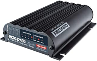
Redarc
Redarc “dual input” DC-DC chargers have integrated MPPT controllers. They appear to do both buck and boost conversion as solar input voltage is 9v-32v.30)
solar+alternator behavior
starter battery maintenance behavior
These units do not appear to maintain the starter battery from solar. Redarc does document how to insert a switched relay in between the starter and aux batts to self-jumpstart.
Ring Automotive
Ring makes a 30A DC-DC charger with 50v max input MPPT. (manual)
Note: the Ring appears very similar to the Kisae (above).
Hardkorr
Korr Lighting makes 25A and 40A DC-DC chargers for the Australian market. These units have Bluetooth connectivitiy. (manual)
- Solar input range is 16v-24v. MPPT algo starts at 16v and disconnects at 10v.
- alternator input range is 12.5v-24v.
- alternator charging connection when chassis voltage ≥13.0v (>12.5v with D+ energized). Disconnect when chassis voltage <12.5v (10.5v with D+ energized_
The manual shows “boost” (lower) and “charging” voltages (higher) and “bulk” voltages. The charging diagram elsewhere in the manual does not use these terms.
solar+alternator behavior
Unclear; the manual does say:
The charger will shift to solar charge mode when the input terminal is connected to the solar panel
…which suggests the unit goes to solar-only mode when panel voltage is detected.
starter battery maintenance behavior
not described
Sterling
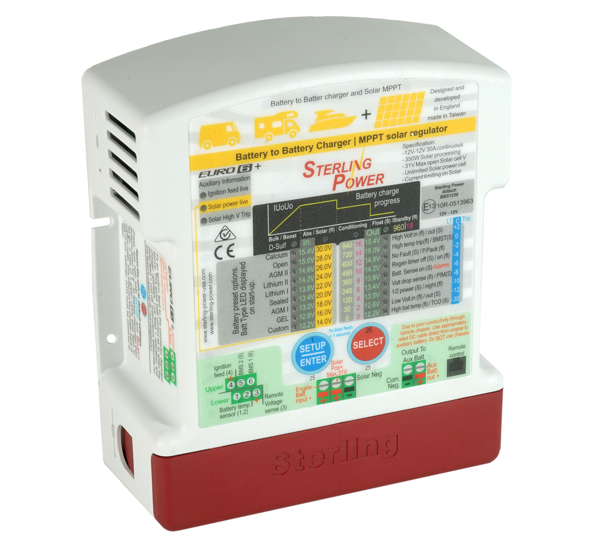
The Sterling BBS1230 Pro Batt Ultra is a 30A boost/buck 30A charger. The solar input max is 31V and 16A with a 350w output maximum. Alternator input voltage is 11v-20v and 30A.
The solar and b2b charging can be turned off separately.
solar+alternator behavior
The charger charges only from alternator when engine is running:
When your engine is running, the BB aspect of the BBS charges. When the engine / ignition is off, the solar charger works. They do not work simultaneously.
starter battery maintenance behavior
the manual for the pre-2022 version incorrectly claims the unit maintains the starter battery.
Votronics Triple
The Votronics Triple is DC-DC, MPPT solar, and shore power charging from 110v-230v, 45Hz-65Hz.
The naming convention is shore power amps33) / DC-DC amps / solar wattage
- VBCS 30/20/250, so 30A from shore, 20A from the alternator, or up to 250w of solar
- VBCS 45/30/350
- VBCS 60/40/430
Max solar input voltage for all models is 36Voc. Minimum panel wattage is 50w-60w depending on model.
solar+alternator behavior
Solar can be prioritized over shore power charging. The Solar Operation section of the manual suggests that alternator charging has priority over solar. The default priority appears to be:
- shore power
- alternator
- solar
starter battery maintenance behavior
The starter battery will be maintained at ≤5A by solar or mains charging. Max input voltage is 32v.
Wagan
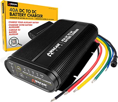
Wagan sells 25A and 40A DC-DC chargers with MPPT inputs. The 32v max input and other specs suggest internals may be similar to Redarc units (see above).
Note: the LiFePO4 profiles charges to 14.5v and floats at 13.6v. The STD and GEL profiles have slightly lower voltages and may be worth considering.
manual (pdf)
solar+alternator behavior
The default behavior appears to be:
- charge by solar if sufficient to meet needs
- if solar is insufficient and engine is running switch to alternator-only
if solar input power is strong enough. When solar input cannot provide enough energy to charge the battery, the Battery Charger will draw power from the alternator.
There is a solar priority mode:
Press the Solar Priority button to prioritize input from the solar panel over charging from the alternator… As long as the solar panels produce more than 25W (for 7410) or 50W (for 7411) of power, the unit will select charging by solar. If the auxiliary battery decreases below a certain level, the unit will charge by alternator regardless of solar input.
This mode appears to be:
- charge by solar if solar harvest is ≥25w/50w even if the vehicle is running
- if solar harvest drops below 25w/50w switch to alternator
Atem Power
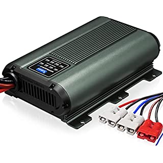 Atem Power makes 40A and 60A combo units (for the Australian market?)
- alternator input: 12.5v - 16v. Connects at 13v, or 11.5v with smart alt (D+ trigger)34)
- solar input: 16v - 25v
- Absorption voltage appears to be 14.v - 14.7v depending on battery type
- touts “soft start” feature that seems to be a gradual ramping up of demand on alternator
- Amazon reviews suggest the Li profiles use a stop-and-drop35) approach like Renogy (ie, no Float setting)
solar+alternator behavior
Solar or alternator, with alternator priority:
Our charger utilizes the DC source before tapping into solar power36)
starter battery maintenance behavior
Reverse Charging Ready: Don't let a flat starter battery hold you back! Our charger swiftly breathes life back into your battery to get you back on the road in a flash.37)
Eco-Worthy
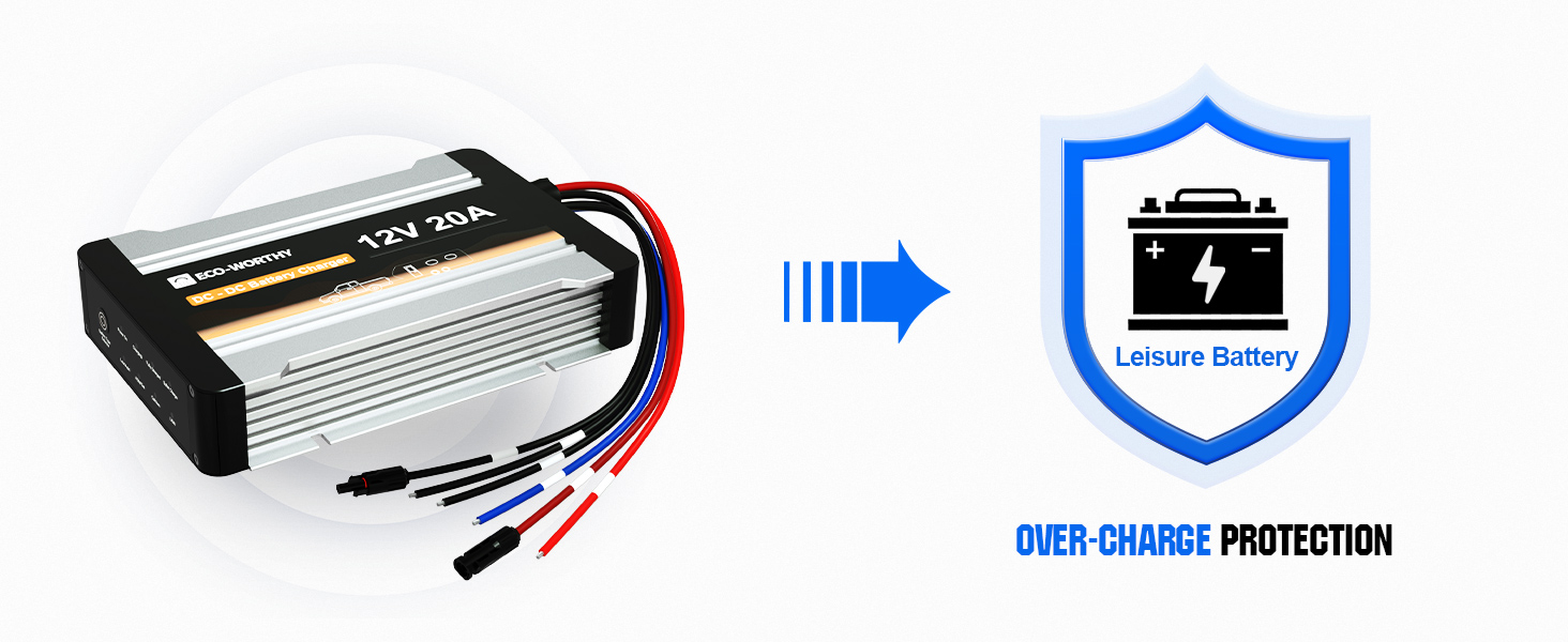
Eco-Worthy makes 20A and 40A combo units.
[Note from secessus: output is reported to be low and it's unconfigurable other than for battery type, but it's 1/2 the cost of similar combo units. Pick your poison]
- starts alternator charging when the starter batt is ≥12.5v.
- Alternator input: 12.4-16.0 Volts
- Solar Input: 16.0-25.0 Volts
- setpoints do not appear to be configurable:
- Absorption: 14.7V (AGM/Gel) 14.4 V (Lead Acid) 15.4V (Calcium) 14.4V(LiON)
- Float: 13.5V (AGM/Gel) 13.5V (Lead Acid) 13.5V (Calcium). No float for LiFePO4, and no reBulk setpoint is given. An Amazon review suggests it rebulks lithium at 13.0v.
solar+alternator behavior
At 0:10 of this video it claims the unit charges from one source at a time:
at a time, leisure battery can only be charged by one of them
at 0:30 in the video it displays the text ALTERNATOR CHARGING PRIORITY and the voiceover seems to confirm this.
starter battery maintenance behavior
There appears to be no starter battery maintenance.
Adventure King
?u=https%3A%2F%2Ftse3.mm.bing.net%2Fth%3Fid%3DOIP.6oFbbYmpMC_NSCsH5UjbHwHaE8%26pid%3DApi&f=1&ipt=f61998a83d6f088b39c568f0f6a833c3449823634d5043709490cfb6072eb61f&ipo=images AK makes a 25A combo unit with a
solar+alternator behavior
starter battery maintenance behavior
CTEK D250 series
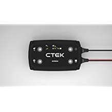 One of the first combo chargers on the market was the D250 series, all of which are 20A smart chargers with integrated MPPT:
- D250 (pre-2018, discontinued) - the original, Vabs == 14.4v, Vfloat == 13.6v.
- CTEK D250SA, a 20A solar/alt controller. Vabs selectable 14.4v and 14.7v. Vfloat 13.6v. Added support for smart alternators.
- D250SE which has 14.2 Vabs and 13.3 Vfloat for lithium settings.
House and starter batteries are combined when the starter battery holds >13.1v for 5 seconds.40) The batteries are isolated when the starter battery is “<12.8V, for 10 sec… or service battery voltage > starter battery voltage”.
Note: the CTEK D250SA41) panel voltage (Vpanel) maximum is 23v.42) There are user reports that the unit is repairable after overvoltage or polarity damage.43),44)
The MPPT charger will charge the house battery at up to 20A. CTEK specifies 50-300W of panel, though the 23v Vmax limits the unit to nominal 12v panels. Note: polycrystalline panels may be more useful here, as their Voc should be a bit lower than mono.
solar+alternator behavior
The 250-series will charge simultaneously from solar and alternator up to the 20A output limit. No details are given in the manual.
with Smartpass
The SmartPass accessory adds up to 80A-120A (see below) of alternator charging to the D250's output under certain conditions for a theoretical charging max of 100A-140A, depending on version:
- Smartpass 80 - original model. 80A + 20A = 100A.
- Smartpass 120. 120A + 20A = 140A.
- SmartPass 120S as above, but with support for smart alternators.
The Smartpass is effectively an isolator (details here), which means it can only charge the house battery at alternator voltage.45)
- during early Bulk stage the combined max charging will be present. Actual charging current will depend on bank acceptance, wiring resistance, alternator voltage etc.
- as house bank voltage rises the 20A DC-DC will continue pushing ~20A46). Isolator charging current tapers, as is normal for them.
- when house battery voltage > alternator voltage the Smartpass can no longer contribute. MOSFETs keep current from leaking backwards through the Smartpass back to the chassis. The 20A DC-DC continues voltage-boosted charging through Absorption 47) and eventually Float if enough time is available.
The smartpass also adds a form of self-jumpstarting.
Related: see this article on DIY “smartpass” functionality
starter battery maintenance behavior
The D250SA trickle charges the starter battery from a solar panel at intervals of 3 seconds if the service battery is fully charged.48)
examples - standalone
Sterling
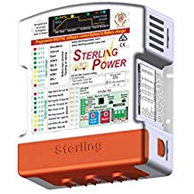 The Sterling Pro Batt Ultra series can be configured to exact setpoints. The BB1260-12 is a 30A example (manual) and costs about $50 more than the D250S above. Note that Sterling rates DC-DC chargers on input, not on output.
The BB1240 has a starter battery maintenance (reverse charging) feature. This might be true for all the 2022 (“red case”) redesigns.
Renogy
DC1212 series
DC-DC chargers in 20A, 40A, and 60A output. Switched on by ignition circuit on the D+ port, low output mode (12.5% of rated current) triggered by 12v on a dedicated terminal. 49) DIP switches for battery type, Vabs and Vfloat. manual (pdf) teardown Note: some versions of the manual may have a typo.
These chargers appear to have a 3 hour absorption duration. This is usually insufficient for lead chemistries, but still longer than the 2 hour duration of the DCC series above. From the manual:
By default, absorption will not exceed 3 hours to prevent overcharging.
Rego series
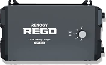 60A DC-DC with different form factor and a configurable USER profile. Important differneces from teh 1212 line above:
- configurable output current - 60A/50A/40A/30A/20A/10A
- voltage-sense triggering rather than D+
- 10-300min boost duration in USER mode
- 120min boost duration still hard-coded in predefined lead-chemistry modes, BUT will drop to Float if output is less than 3A (ie Absorption termination based on endAmps)
manual (pdf)
Redarc
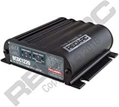 Redarc makes DC-DC chargers in 20A and 40A sizes.
They have modes for “AGM, gel, calcium content, VRLA and standard lead acid batteries”.
Victron
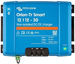
Victron makes several DC-DC chargers, some of which are configurable by bluetooth. 12v examples:
- Orion-Tr 12|12-20 20A
- Orion-Tr 12|12-30 30A (most popular model)
See information on isolated v. non-isolated chargers above.
Low-temp protection can be added by using a 12v temperature controller to disable the charger via the the Orion's remote ON/OFF switch.
Be aware the physical jumpers may have a specific orientation.
Orions tend to run hot50) so mount in an area with sufficient ventilation.
This YT video covers Orion configuration in considerable detail.
Bogart
Bogart's SC-2030 can work as a DC-DC charger as well as a PWM charge controller.
Leaptrend
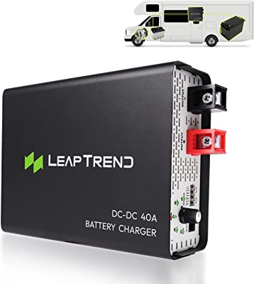
Leaptrend makes DC-DC chargers in 20A, 40A, and 60A versions.
- 10-16v input
- D+ triggering only
- physical switch for battery type
- current-limiting terminal for half power
- power supply mode (13.2v)
Votronics
Votronics makes a range of standalone DC-DC chargers
- VCC 1212 series (12v alternator → 12v bank), in 20A, 30A, 50A, 70A, and 90A
- VCC 1224 series (12v alternator → 24v bank in 25A
- VCC 2412 series (24v alternator→ 12v bank) in 25A, and 45A
- VCC 2424 series (24v alternator→ 24v bank) in 25A, and 45A
The chargers can be activated by D+51) wire52) and disconnects <11.2v after 30 seconds.
When sensing voltage it connects at >13.3v, reduces charging at <13.0v, and disconnects at <12.9v after 30 seconds.53)
starter battery maintenance behavior
The starter battery will be maintained with ≤1A current when lead banks are >13.1v, and when lithium banks are >13.5v.54)
examples - without current limiting
The Sterling A2B uses DC-DC conversion to boost voltage but has no ability to limit current.
examples - 12v to 24v
Charging a 24v bank from 12v alternator is possible but gear selection is relatively slim.
Victron makes 12/2455) DC-DC chargers with inputs 8-17v and outputs of 20-30v.
- Orion-TR 15A, non-isolated
- Orion-TR 15A, isolated
- Orion-TR 5A, IP43, isolated
Also see the Votronics section above for their DCC 25A 1224 charger.
installing inline with a relay
Sometimes we want to replace an existing relay charging setup with DC-DC. There are some things to consider
- it does not matter where a relay is installed, so it is typically installed in the engine bay.
- DC-DC, on the other hand, should be installed as close to the house battery bank as practical to avoid voltage sag.
- some DC-DC are triggered only by D+, meaning long wire runs to the cabin to get this signal. The relay is providing this signal for us on the main POS wire, since it has its own trigger and only sends power when triggered.
For these reasons it is sometimes preferable to leave the relay in place and install the DC-DC downstream from it:56)
starter battery -> relay -> POS wire to the living area -> DC-DC charger -> battery bank
Caveat: if the DC-DC has a starter battery maintenance function and you want to use that then the relay should be removed. Otherwise the circuit will be broken by the relay with the key off so power cannot flow back to the starter battery.
gotchas
DC-DC chargers are typically rated on their output power, which means they can pull more than their rating from your alternator. This could be a consideration if you are running a small alternator and relatively big DC-DC.
Example: Relatively low chassis voltage, 13.4v. Relatively high charging voltage, 14.8v.57). 50A output @ 14.8V requires 57.98A from the alternator after DC-DC boosting and losses.
Carefully observe voltage input maximums on units with built-in solar charge controllers. If you will be in freezing conditions allow headroom to account for the effects of temperature on solar cell voltage.
Voltage-sensing units58) can misbehave when an undersized starter battery charger/maintainer is attached. For this example we assume a 10A maintainer and a 20A DC-DC charger.
- starter battery voltage rises from 10A maintainer charging…
- triggering the DC-DC charger…
- which begins pulling up to 20A from the chassis
- pulling down the starter battery since the 10A maintainer cannot keep up
- starter battery voltage drops far enough the DC-DC turns off
- repeat forever
The workaround is to either charge the house battery first or to buy a big enough starter battery maintainer to support both the starter battery and DC-DC charger loads.
further reading
DC-DC charger (B2B) options and general discussion on DIY Solar Power Forum.

