
electrical:solar:charge_controller
This is an old revision of the document!
Table of Contents
Words of wisdom: “Any Solar is better than no solar, but having too much solar is difficult. The best solar systems are those which can keep the batteries the happiest. Happy batteries are those which are recharged quickly after depletion.”1) - SternWake
Solar charge controllers
A solar charge controller (CC) regulates the charging of a battery bank from the solar panels. Counterintuitively, the primary job of the charge controller (CC) is to keep the batteries from being overcharged. Solar panels run at higher voltages than batteries, often at voltages high enough to damage the batteries. The CC provides the correct amount of power the battery needs at the correct time; this is called smart or three stage charging. Charge controllers are generally rated by the amount of output they can provide. This output is shared by charging circuits and LOAD circuits. For example, a 20A controller might be using 18A for charging and have 2A available for LOAD. Controllers operate based on factory- or user-defined setpoints (values) stored internally.
types of charge controllers
[note from frater secessus: PWM vs. MPPT debates can get overheated in forums and comments. It's your money and your build so do it the way that meets your needs.]
PWM
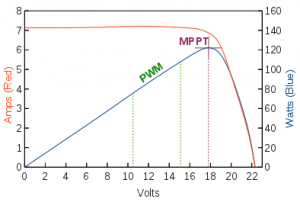
 PWM (pulse width modulation) controllers charge by connecting panels to battery until a given voltage setpoint is reached. When the desired setpoint is reached the controller switches current on/off to the battery in very fast cycles and in such a duration needed to keep voltage from rising. This time slicing power delivery is called is pulse width modulation, or PWM. Some heat will be generated by the switching. Counterintuitively, the PWM may be cooler the touch when it is running full open because there is no switching going on to limit voltage.
 This runs the panels at2) battery voltage (Vbatt). Vbatt is usually much lower than the panels' Vmp3) and so PWM generally cannot capture the panels' maximum available power4) under typical conditions. A side effect of this is the PWM controller will have highest power output when Vbatt is highest: Absorption (Vabs) and Float (Vfloat). Setpoints can be tweaked for longer duration Absorption and higher Vfloat to maximize power output of a PWM controller.
PWM controllers are simple, inexpensive, and sufficient for many uses, particularly if ambient temperatures are fairly high, paneling is ample, and batteries are not deeply cycled.
This runs the panels at2) battery voltage (Vbatt). Vbatt is usually much lower than the panels' Vmp3) and so PWM generally cannot capture the panels' maximum available power4) under typical conditions. A side effect of this is the PWM controller will have highest power output when Vbatt is highest: Absorption (Vabs) and Float (Vfloat). Setpoints can be tweaked for longer duration Absorption and higher Vfloat to maximize power output of a PWM controller.
PWM controllers are simple, inexpensive, and sufficient for many uses, particularly if ambient temperatures are fairly high, paneling is ample, and batteries are not deeply cycled.
Note that there are some simple PWM controllers like Morningstar's SunGuard that run at a single voltage.
For technical reasons PWM can deliver more current than the panels' Imp, even nearing Isc.
MPPT
 MPPT (maximum power point tracking) controllers have two defining abilities:
- discover (track) and utilize various power points along the panel's power curve. Sometimes this is the maximum power point (MPP); often in a 'dweller context the system needs less power and the controller runs the panels at some other power point. It might be more accurate to call them PPT controllers.
- DC-DC downconvert excess voltage to amps - this is possible because MPPT decouples panel voltage (Vpanel) from charging voltage (Vbatt)
When maximum power is required5) the controller will run the panels at Vmp (the maximum power point). At other times the controller will find a less-than-maximum power point to match panel output to system needs.

Since panel voltage at a given power point is usually too high for system needs6) the controller performs a DC-DC conversion to bring the voltage down to a directly usable level. Because current through a conductor is directly proportional to voltage7) this downconversion effectively turns excess voltage into increased amps.(minus conversion losses).
This ability to decouple panel and bank voltage can result in 10%-30% more power harvested from 12v nominal panels than with a PWM controller. Marketers like to call this “boost” or “gains” but it really just full capture of whatever power the panel[s] can provide under given conditions.
"boost" effect
 When compared apples-to-apples on identical systems with only the controller being different, the “boost” effect is most pronounced:
- during bulk stage and the early part of absorption stage when the battery can take in the most power
- anytime the system is fully loaded down (charging and/or loads)
- when the battery is most depleted (ie lowest resting voltage). This is the result of a cascade of factors:
- When a battery is deeply discharged it will go into Bulk charging mode until it reaches the Absorption voltage (Vabs). For the purpose of illustration we will assume the bank is depleted to 12.2v (~50% state of charge), a commonly recommended lower limit for deep cycle batteries.
- PWM controllers can only run the panel at whatever voltage they are charging at right now. In our example that is 12.2v.
- Nominal 12v panels usually have max power output (Vmp) around 17v.8)
- during times of greatest PV efficiency11) (clear, cold weather)
There are some considerations when designing a system around an MPPT controller.
shunt
 In this usage, shunt controllers are single-stage chargers that hold the bank at a setpoint (Vdisconnect)14) as long as sufficient solar harvest is present. When the setpoint voltage is achieved the controller is turned off for some amount of time.15)
Technical note: shunts short out the panels to control ON/OFF charging. Series chargers behave similarly but open-circuit the panels. PWM is like a superfast series charger whose ON/OFF cycles are so fast that an average voltage can be held.16)
Simple versions use simple electronics17) or relays to turn charging on until Vdisconnect is reached, at which point charging is turned off off. If/when voltage falls to some lower voltage (Vreconnect) charging begins again. This is sometimes called charge and stop charging or on/off charging. Voltage tends to wander a bit as the charging stops and starts. They are often used where extreme simplicity/robustness is required, or where more complex electronics might cause electrical interference.18)
More complex shunts use electronic components19) to hold the single voltage setpoint with finer accuracy, dissipating switching heat through the backplate or other heatsink. The difference is mainly one of time and therefore stability of the setpoint; a relay shunt might go ON/OFF 1x/second every few seconds if the loads were neatly balanced with solar harvest. The electronic shunt might switch power tens, hundreds or thousands of times each second and may be PWM or quasi-PWM. It would take an oscilloscope to know for sure what's happening under the hood.
For the purposes of this discussion the two types will be grouped together.
…PWM [and] shunt controllers apply full panel voltage, or something close to it, across the battery terminals, at a duty cycle (fast for PWM, slow for shunt) that keeps the battery happy, and the controller monitors the battery voltage and then adjusts the PWM duty cycle accordingly, or in the case of a [relay-based] shunt, it clamps the panel output. – Tx2Sturgis20)
They may be hardcoded with setpoints or allow user configuration. If configurable, you can get better results by choosing setpoints to fit your situation. Usually on cheap shunts there is one setpoint, which we can think of as the absorption voltage (Vabs). Holding Vabs as long as the sun shines might seem weird but to quote Sternwake again:
If your charge controller only holds [absorption] voltage for an hour or two, that is likely not enough time. As long as [there is a load] and you cycle the battery daily, you could set float voltage to 14.8v [to match absorption] without worry. Only when you stop cycling the battery do you need to return float voltage to more regular 13.2v levels. Premature application of float voltage by automatic charging sources is a battery killer.21)
USB converters
 These aren't controllers in the normal sense, but there are modules that connect to your panel's MC4 connectors and output USB power.
If you only need 5v USB power up to 2.5A per port this may be a workable solution.
DDCCC
[note: this is a placeholder for a possible new entry.] There are DC-DC converting charge controllers (DDCCC) appearing on the market that claim to be MPPT but do not actually track power points (maximum or otherwise). They do downconvert some excess voltage into amperage. See this blog post.
how to choose
PWM is a reasonable default choice in typical scenarios22); they work well enough and are inexpensive. PWM controllers can cost half or a third of their MPPT workmates for any given rated output.23) If more power is needed (and there is physical space) additional PV can be added to match the charging output of an MPPT charger, often at a lower cost. [There are no prizes for fanciest or most expensive charge controller! Do what is best for you – frater secessus]
There are also edge cases where PWM can actually make more power than MPPT. An example of this might be low-Vmp poly panels during Absorption stage in very hot weather, due to MPPT DC-DC conversion losses and temperature derating.
MPPT is effectively required when:
- using panels with nominal voltages higher than 12v 24). To be fair, one really can use higher-voltage panels with PWM and 12v banks – they just end up running at about half power.
- space available for panels is limited, as on a sailboat or small vehicle
- daytime loads are hampered by PWM Vbatt hobbling
- making DIY converters
Further reading: an excellent and readable whitepaper by Victron (PDF).
MPPT may be a better fit when:
- the existing PWM system is not providing enough output
- nominal 12v panels have a relatively high Vmp (>=18v) for reasons discussed here.
- battery banks are cycled deeply on a regular basis so more time is spent at low Vbatt where PWM struggles.
- with deeply-discharged banks of low internal resistance (AGM and especially lithium). Their voltage will take more time to rise from deeply-cycled levels.25)
- charging is by solar only; no generator, shore power, or alternator charging to help.
- if temperatures are very low (rising Vmp means increasing output which PWM could not capture)
- the increase in cost is not an undue burden
Shunt controllers are extremely inexpensive, making them useful for even very small systems, test configurations, and backups.
Shunt may be the best fit::
- when price point is critical, as in shallow-cycling configurations
- when very little space is available to mount the controller
- when used off-grid with deeply-cycled lead banks (eternal absorption)
- Their simple ON and OFF setpoints may also make them useful for holding lithium chemistries at quasi-Float voltages.
See also shunt tweaking.
multiple charge controllers
Multiple controllers (with separate arrays) can be used to charge a common bank. The controllers should be configured with similar charging setpoints for the greatest efficiency.26)
sizing your charge controller
As with inverters, sizing the controller correctly will help system efficiency and save money. An oversized CC will have unnecessarily high parasitic drains as it powers itself and will cost more. An undersized CC will not be able to put all the rated solar wattage to use and will leave no room for expansion. For PWM controllers, the formula is something like (panel wattage / 13) * (1.2 oversize for safety) = charge controller amps.27) MPPT controllers have more leeway in sizing since they can control the output of the panels independently of battery voltage. See also Sizing a Solar Installation
overpaneling
this section has been moved.
Using LOAD output
It is common for charge controllers to have a LOAD output for powering (or switching) loads. One benefit to doing this is you can define a Low Voltage Disconnect (LVD) setpoint and Low Voltage Reconnect to protect the battery from excessive discharge:
The load outputs take power from the battery terminals…. the only advantage in using the load terminals is displayed info and the ability to disconnect the load at programmable voltage levels. – mikefitz28)
Not all types of loads should be run from these terminals, though. Morningstar says:
Heavily inductive or capacitive loads such as pumps, motors, compressors, and inverters should not be wired to the controller’s Load terminals. In addition, loads exceeding the Load Current Rating of the controller should not be connected to the controller’s Load terminals.29)
elsewhere they say:
Inductive loads can generate large voltage spikes that may damage the controller’s lightning protection devices.30)
although an exception is made for the SunSaver MPPT which “Handles inductive loads without problems.”31)
One can run loads heavier than the controller is rated for (or inductive/capacitive loads) by connecting those load[s] to a relay32), which is in turn connected to the LOAD output. This still allows for Low Voltage Disconnect because the CC will turn off power to the LOAD output, which turns off power to the relay, which turns power off to the load.
You may also be able to use the LOAD output to create a separate 12v circuit for non-essential ("opportunity") loads.
Note: in wind and hydro power applications the output can be sequenced so that LOAD is activated only when batteries are fully charged. This is called a “dump load” because those power sources need to be able to “dump” excess current to prevent damage to themselves. Dump loads are not necessary in solar because panels can be open- or short-circuited without damage.
positive ground controllers
Some controllers are labeled or described as “positive ground”, often by their competitors. The term is incorrect and misleading:
… “positive ground” terminology is wrong. There is nothing connecting positive supplies to chassis ground, earth ground, or any other ground. – Trebor English33)
A more accurate term would be Low Side Switched Controllers (LSSC hereafter). A how and why of low side switching is found at the end of the article. These LSSC can be incorporated into your camper's electrical system as long as:
- anything powered by the LOAD output does not ground the negative wiring to the vehicle.34)
- any communications i/o (like ethernet or other jacks) do not connect to devices that are grounded to the vehicle.35)
- solar panels are wired directly to the controller and do not use the vehicle as an electrical path36)
If you are not using the LOAD output, communicating with the controller, or using the vehicle as an electrical path for the solar panels, LSSC (so-called “positive grounding”) doesn't matter.37)
use of LOAD output on an LSSC
If some basic steps are not taken the device may not turn off/on as expected. Here are some appropriate ways to use the LOAD output with LSSC:
- run all positive and negative wires back to the LOAD output; or
- run them through buses that lead back only to the LOAD output; or
- put a relay on the LOAD output and run all the loads through that.38)
low side switching
LSS means switching (turning on-off) is done on the negative (or low) side rather than on the positive (or high) side. Referring to a low side switched PWM controller, Trebor says:
All three plus connections, solar panel, battery, and load, are tied together. Loads are turned on with a switch (transistor) between the load minus terminal and the battery minus terminal. Charging is turned on (bulk) or pulsed with a switch between panel minus terminal and battery minus terminal.39)
He goes on to explain why this is the case:
The reason for the low side switching is the intersection between physics and economics. N-channel field effect transistors are faster, better, cheaper than P-channel parts. The designer can A) use good parts in a simple circuit or B) use more expensive not so good parts or C) make a complicated circuit that uses 18 volts to control a 15 volt switch.40)
2)
or very close to
3)
unless the panels are very hot
4)
adjusted for temperature, insolation, etc
5)
in Bulk or at other time when loads + charging >= panel output
6)
particularly with higher than nominal 12v panels
9)
Iop = 5.6A
10)
there are minor inefficiencies not considered here
11)
i.e. highest voltage
12)
this is a function of higher input voltages
14)
whether generally or exactly
15)
In a hydro or windpower scenario the power cannot be turned off and is diverted (shunted) instead to a diversion load like water heating, water pumping, etc.
16)
it actually does it by varying the width of the ON periods, resulting in a percentage of ON time
17)
as with Flexcharge
18)
as in a ham shack
19)
like FETs
22)
12v house power, 12v panels
23)
10A, 20A, 40A, etc
24)
more precisely, when panel nominal voltage exceeds house bank nominal voltage
33)
PM correspondence with frater secessus
electrical/solar/charge_controller.1633396239.txt.gz · Last modified: 2021/10/05 01:10 by frater_secessus
affilliate disclosure | the RVwiki runs on a virtual server from NetCup
Except where otherwise noted, content on this wiki is licensed under the following license: CC Attribution-Noncommercial-Share Alike 4.0 International
